Writing
Blog
Product notes, engineering write-ups, and lessons from building, operating, and buying software at CodeConda.
Auto-Generate Titles, Descriptions, and Keywords for Matchbook Cover Product Listings with AI
Are you a collector or reseller of vintage matchbook covers looking to list your products faster and boost visibility on eBay, Etsy, or your own Shopify store? If so, you’ll love ShopTag.ai. It’s an AI-powered product listing generator designed to help you create search-optimized titles, descriptions, and keywords in seconds.Whether you’re selling rare advertising matchbooks, restaurant matchbook covers, or hotel and motel matchbooks, ShopTag.ai makes the listing process easier, faster, and more

How To Drive Website Traffic in Global Markets
When companies expand internationally, they often face a choice between standardizing their approach globally or adapting to local markets. A multi domestic strategy takes the latter path, focusing on customizing products and services for each specific market rather than using a one-size-fits-all approach.
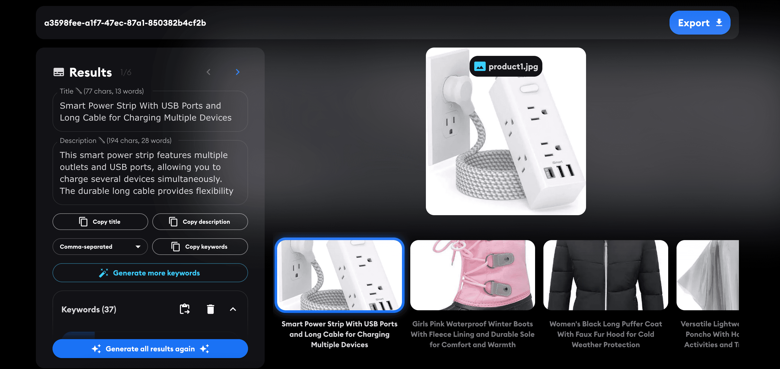
ShopTag.ai: AI Product Tagging and Categorization
With ShopTag.ai, you get expertly written product listings tailored to meet the demands of today’s competitive eCommerce landscape. From clear and engaging titles to detailed descriptions that highlight your product’s benefits, ShopTag.ai helps your products perform better online.
How to Translate Your Wix Site on a Budget
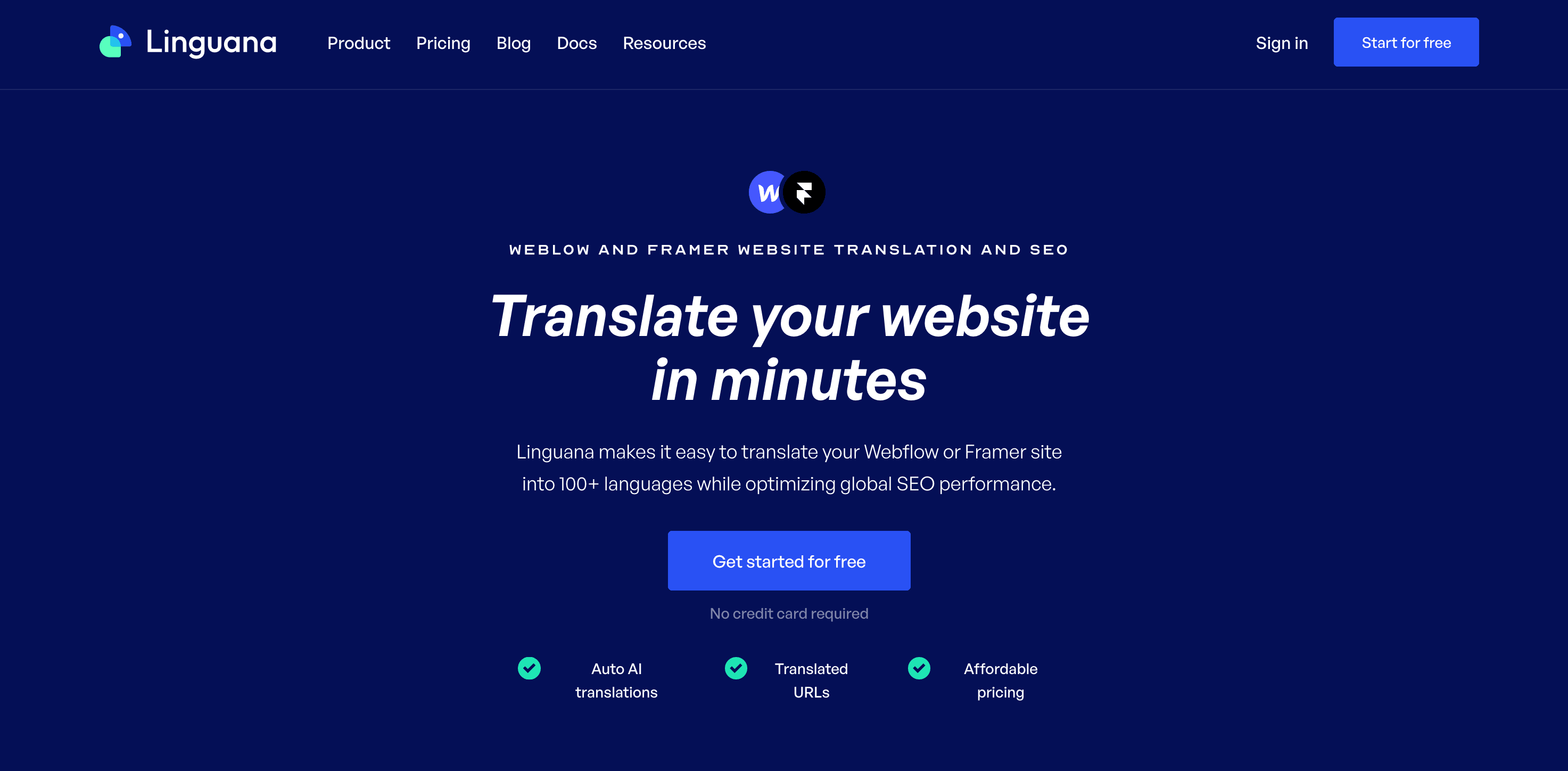
One cost-effective alternative is Linguana, offering plans starting at just $19 per month, with a maximum monthly plan of $99. This is significantly more affordable compared to other options and provides flexibility since AI translation credits are purchased separately as needed.

Translate your Carrd landing page with Linguana
Creating a Carrd website is a fantastic way to establish an online presence quickly. But if you want to connect with a global audience, offering your content in multiple languages is essential. Linguana is the perfect tool to help you achieve this.

How to Translate and Localize Your Webflow Website
When it comes to translating Webflow sites, Linguana stands out as the top choice. Linguana is built specifically for Webflow and adheres to the best SEO practices.

How to Automatically AI Translate i18next JSON Files
Follow this guide to learn how to translate your source i18next JSON file into any language. Works with any framework supported by i18next, including React, Next.js, Angular, Flutter, Svelte, and more.
PhotoTag.ai Rolls Out Enhanced AI Model for Metadata Generation
PhotoTag.ai, a platform specializing in generating metadata for stock photos and videos, has recently upgraded its AI model to improve performance significantly.
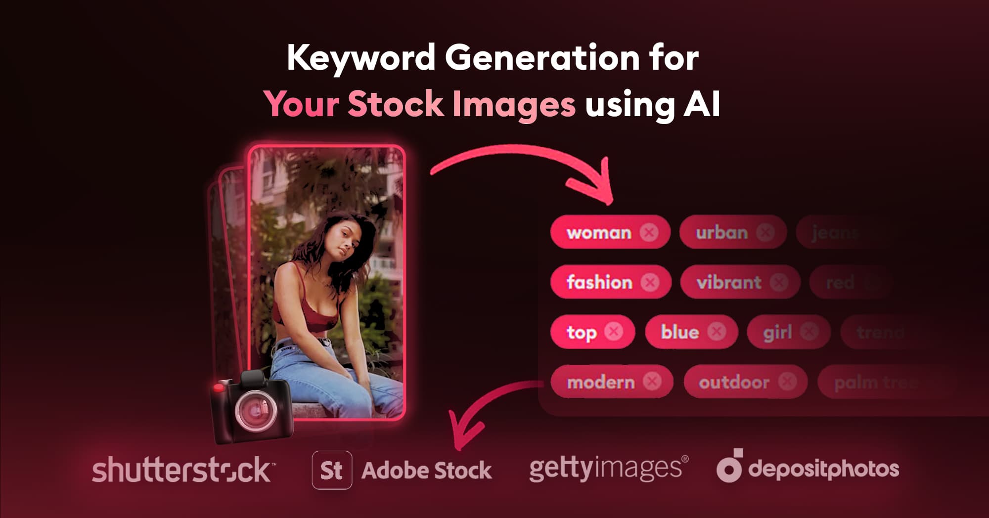
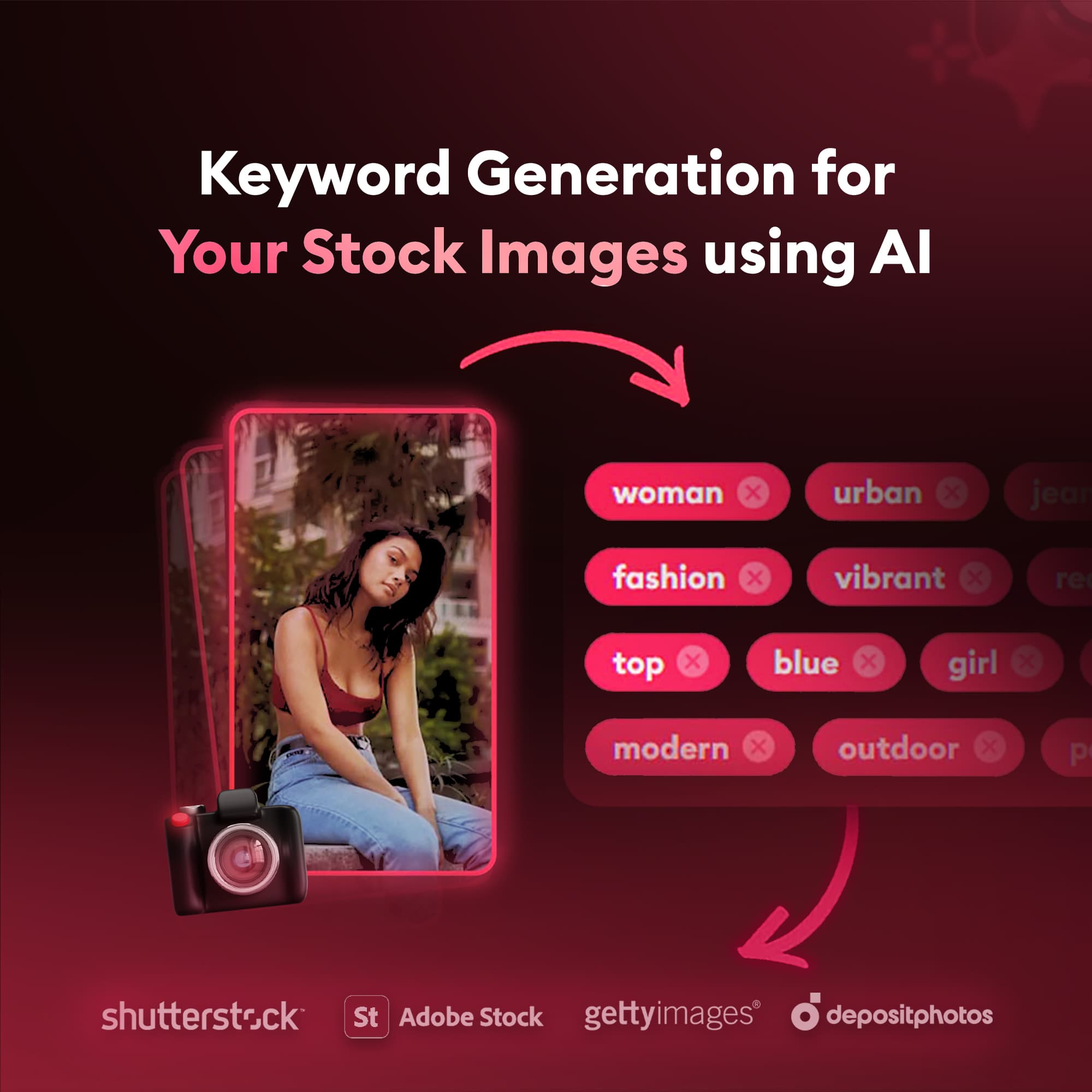
How to generate stock photo keywords, titles, and descriptions with AI
One standout tool in this space is PhotoTag.ai. In this post, we’ll walk you through how to use PhotoTag.ai to streamline your workflow and optimize your metadata.